
In the Bavarian research project 5G TODAY the project partners IRT, Rohde & Schwarz and Kathrein Broadcast have implemented the FeMBMS (Further Evolved Multicast Broadcast Mobile Service) specification and set up an “LTE-based 5G Broadcast” test field in the Bavarian Alpine region with the transmitters Wendelstein and Ismaning. This technology enables highly efficient live and linear video distribution to a high number of mobile devices such as smartphones as well as screens in cars. The project was supported by the associated partners BR and Telefónica Deutschland and co-funded by the Bavarian Research Foundation BFS.
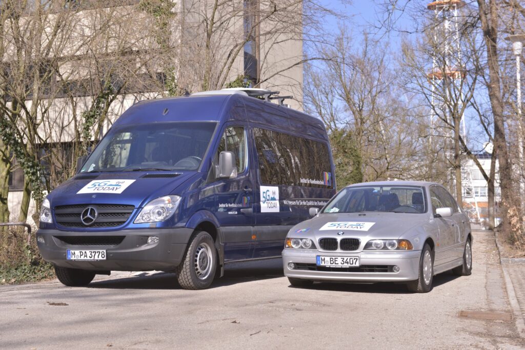
Figure 1: Mobile measurements in the 5G TODAY project
Description of the measurement procedure
From June 2019 to the end of the project in February 2020, many laboratory and field
measurements were carried out to verify coverage and “Quality of
Service”. The tests were done with a measurement system based on an RF
receiver by Rohde & Schwarz and the KSA (Kathrein Signal Analyser) FeMBMS
software from Kathrein Broadcast. The KSA Scanner FeMBMS has been developed during
the project.
The video below shows an overview of the measurements in general. The main
requirements and the expected output are explained briefly further on. The
measurement procedure depends on the used conditions. Moreover, considering the
stationary case where the receiver has a fixed location, the receiver acquires and
decodes the signal at the same time of the reception. At the end of the measurement
the signal quality parameters are saved in the prepared database. In this case, the
system works in a snapshot mode. On the other side considering the mobile case, it
is recommended to split the process into two steps to avoid the gaps in the detected
signal. In the first step the KSA Scanner FeMBMS digitizes the RF signal with a high
sampling rate together with the exact GPS coordinates and saves the I/Q data to a
file. In the second step the KSA Scanner processes the signal from the I/Q file and
extracts the required parameters in terms of the quality of the signal in the
relevant location. Those parameters may involve the effects of the mobile reception
as well as the different PCI (Physical Cell ID) configurations, as we have two
high-power high-tower (HPHT) transmitters using the same frequency and building a
Single Frequency Network (SFN).
Description of a FeMBMS signal
To evaluate the network design, both the Multimedia Broadcast Single Frequency
Network (MBSFN) data signal, with a cyclic prefix (CP) of 200μs, and the Cell
Acquisition Subframe (CAS) signal, with the LTE extended version of CP of 16.67 μs,
were examined. The CAS signal contains the control information required for 100 %
MBSFN broadcast resource allocation and is carried by subframe #0. It is transmitted
at intervals of 40 ms, i.e. it is transported in every fourth LTE radio frame. The
CAS signal is required for both signaling and synchronization. As a result, to
decode the data signal, the CAS signal must first be decoded correctly. This means
that MBSFN coverage is ensured only if both the data signal and the CAS signal can
be received. The CAS signal has relatively a very short CP, which makes it
unattractive for single-frequency operation in HTHP networks. On the other hand, it
is clearly more robust and requires a considerably lower carrier-to-noise (C/N)
ratio than the corresponding data signal. The test field is operated in the
frequency channel 56 and the FeMBMS signal has a bandwidth of 5 MHz.
Results of field tests
First, a qualitative comparison of the measurements with the coverage prediction
calculated by the IRT frequency planning tool FRANSY for a measurement route was
done. As shown in Figure 2, the measured field strength values correlate well with
the simulated values in the coverage prediction along the same route.
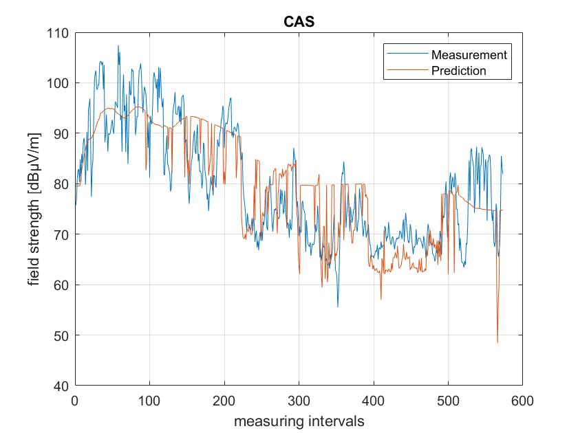
Figure 2: Comparison between the measurements and coverage prediction
However, the measurement does not only consider the power of the signal, but also many other parameters like CINR (carrier to interference plus noise ratio) and BLER (block error rate). Such parameters are vital to the network coverage evaluation and therefore several measurement campaigns were carried out to check the signal quality in different locations. According to the EBU TR 034 [1] the simulated carrier-to-noise (C/N) ratio for MCS9 and mobile reception is 10,4 dB. Figure 3 shows the MBSFN CINRs values for a 63 km long route between the transmitters Ismaning and Wendelstein. The CINRs close the transmitter are higher than 15 dB and it can be assumed that the reception will work well for the mobile case. At the cell edge the CINR is about 10dB or less. That means, in this area the reception could be critical for some locations on the considered route.
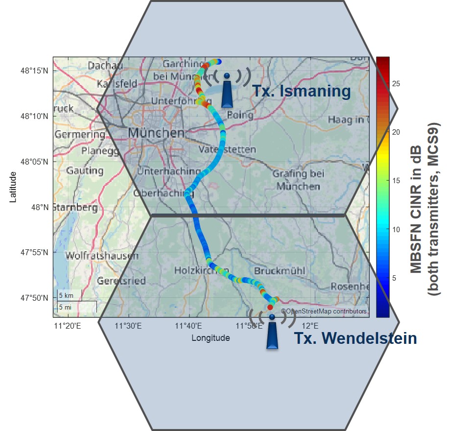
Figure 3: Measurement route in 5G Today
Furthermore, the IRT’s investigations showed that the PCI (Physical Cell ID) configuration set in the CAS does not have big influence on the network gain and self interference of the MBSFN signal, which carries the data signal. It appears, that even in case of different PCIs of the transmitters, there is a certain “SFN gain” in the data part of the signals. A network gain could be also determined for the SFN with two transmitters Ismaning and Wendelstein compared to the single transmitter in MFN operation. The results of the measurements will be published in the final report of the 5G TODAY project, which will be available in autumn 2020.
Watch the demo video
[1] EBU TR 034, Simulation Parameters for theoretical LTE eMBMS Network Studies, Geneva, December 2015